High-voltage power transmission and industrial infrastructure rely heavily on resilient cable insulation to function safely. When electrical networks operate in demanding environments, premature cable failure becomes a significant operational risk. Thermal degradation from heavy loads, moisture ingress in subterranean settings, and chemical exposure in industrial plants compromise standard insulation materials, leading to faults and system downtime. Engineers and project managers must select materials capable of withstanding these extreme conditions without degrading over time.
Cross-linked polyethylene has emerged as the industry-standard thermosetting insulation designed specifically to mitigate these severe risks. By altering the molecular structure of standard polyethylene, manufacturers create a robust barrier that resists high temperatures, electrical stress, and environmental damage. Understanding the technical properties, inherent limitations, and strict procurement criteria of xlpe cables is essential for designing reliable electrical distribution networks. This technical evaluation explores how this insulation technology addresses the core challenges of modern power infrastructure.
Thermal Superiority: XLPE cables sustain continuous operating temperatures of 90°C and short-circuit temperatures up to 250°C, significantly outperforming traditional thermoplastic alternatives.
Dielectric Efficiency: The cross-linking process yields exceptional dielectric strength, making XLPE the preferred choice for medium-voltage (MV), high-voltage (HV), and extra-high-voltage (EHV) networks.
Application Specificity: Optimal for underground, submarine, and heavy industrial applications, though installation requires strict adherence to bending radius and termination protocols.
Table of Contents
Engineers must understand the structural differences in insulation materials to accurately predict long-term performance under electrical load. The fundamental behavior of a cable under thermal and electrical stress dictates its suitability for specific grid applications. Standard polyethylene offers excellent electrical properties but fails mechanically at elevated temperatures. To solve this, the material undergoes a chemical transformation that fundamentally alters its physical characteristics, converting it from a standard plastic into a highly resilient elastomer-like compound capable of handling severe operational demands.
The chemical process of cross-linking, often referred to as vulcanization, involves bonding adjacent polyethylene molecules to form a complex, three-dimensional network. In standard polyethylene, polymer chains float independently, allowing them to slide past one another when heated. During cross-linking—typically achieved through peroxide, silane, or electron-beam irradiation methods—strong covalent bonds form between these chains. This macroscopic molecular web locks the polymer structure in place. The resulting material retains the excellent dielectric properties of the original base polymer but gains immense mechanical stability, preventing the chains from separating even when subjected to extreme thermal energy.
This transformation highlights the critical distinction between thermosetting materials and thermoplastics. Thermoplastics, such as Polyvinyl Chloride (PVC) or standard polyethylene, soften and eventually melt when exposed to heat, losing their structural integrity and insulating capabilities. If a thermoplastic cable experiences a severe overload or short circuit, the insulation can permanently deform, leading to immediate failure. Conversely, cross-linked polyethylene is a thermosetting material. Once the cross-linking process is complete, the material maintains its form under high heat. It will not melt or flow, allowing the cable to endure significant temperature spikes without compromising the safety or functionality of the electrical system.
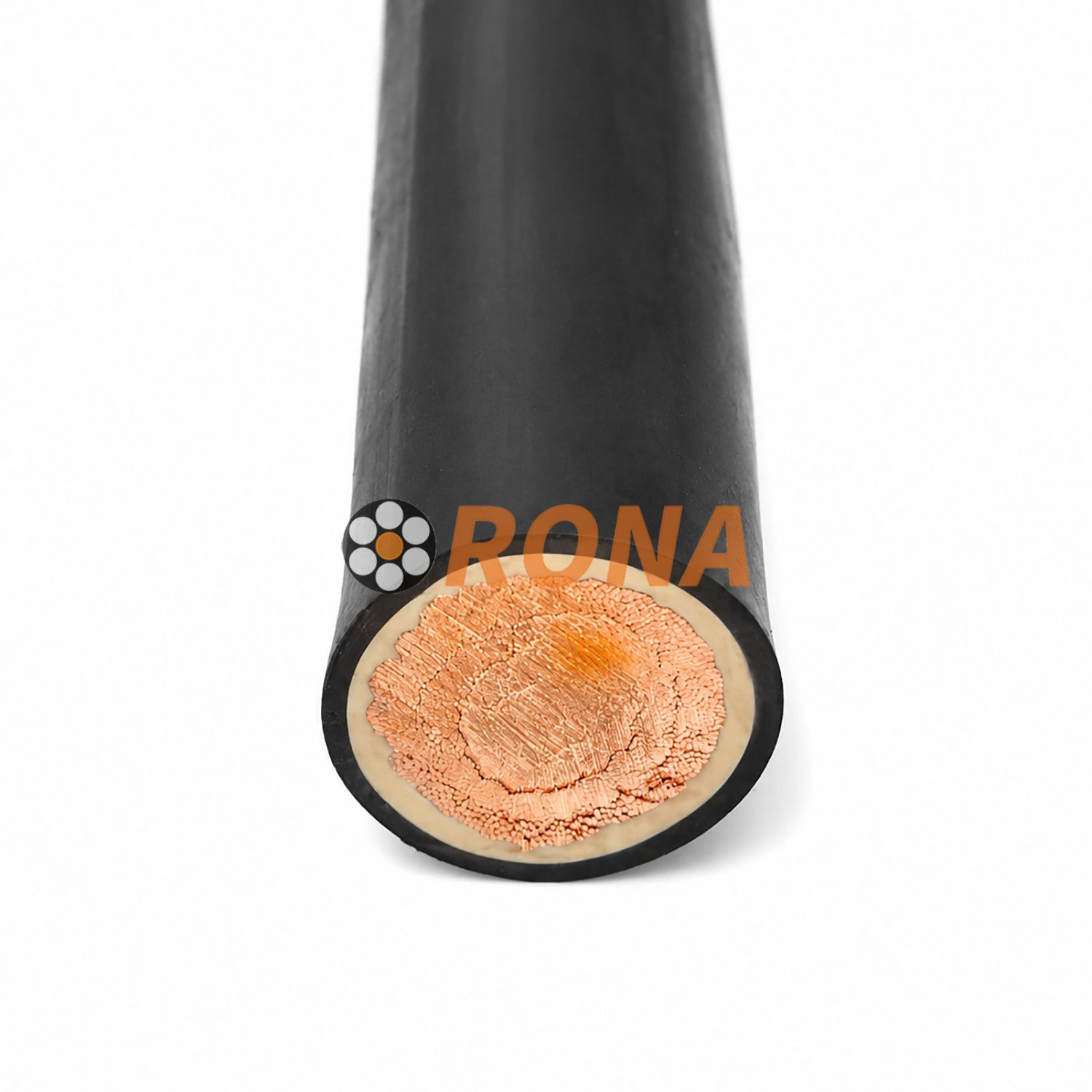
The performance of modern power cables relies on a sophisticated, multi-layered construction where each component serves a distinct electrical or mechanical purpose. The core conductor serves as the primary pathway for electrical current. Engineers typically analyze the choice between stranded aluminum and copper conductors based on project requirements. Aluminum conductors are lightweight and highly cost-effective, making them ideal for long-distance utility distribution, though they require larger overall cable diameters to achieve the same ampacity. Copper conductors offer superior electrical conductivity and allow for more compact installation footprints, which is highly advantageous in space-constrained industrial facilities or underground ducts.
Surrounding the conductor are critical semi-conductive layers. The inner conductor screen and the outer insulation screen play a vital role in managing electrical stress. A stranded conductor has an irregular surface profile, which creates localized areas of high electrical field intensity. The inner semi-conductive screen smooths out this profile, ensuring a uniform electrical field enters the insulation. Similarly, the outer insulation screen confines the electrical field within the dielectric layer. Together, these screens prevent localized voltage stress concentrations that would otherwise cause partial discharge and premature insulation breakdown.
Between these semi-conductive screens lies the insulating barrier itself. This pure cross-linked polyethylene layer defines the dielectric strength of the cable. The thickness of this layer is precisely engineered based on the intended voltage rating of the system, ranging from a few millimeters for medium-voltage applications to significantly thicker profiles for extra-high-voltage transmission lines. The purity of this layer is paramount; any microscopic voids or contaminants introduced during the extrusion process can act as initiation points for electrical failure.
External to the insulation screen is the metallic shielding or sheath. Typically constructed from copper tape, copper wire screens, or extruded lead, this layer serves two primary functions. First, it confines the electromagnetic field within the cable, preventing interference with nearby communication lines or equipment. Second, it provides a low-impedance return path for fault currents. In the event of an insulation breach, the metallic shield directs the massive short-circuit current safely to ground, triggering protective relays and preventing catastrophic damage to the surrounding infrastructure.
For installations subject to physical hazards, armoring systems provide necessary mechanical protection. The selection of armor depends entirely on the cable configuration:
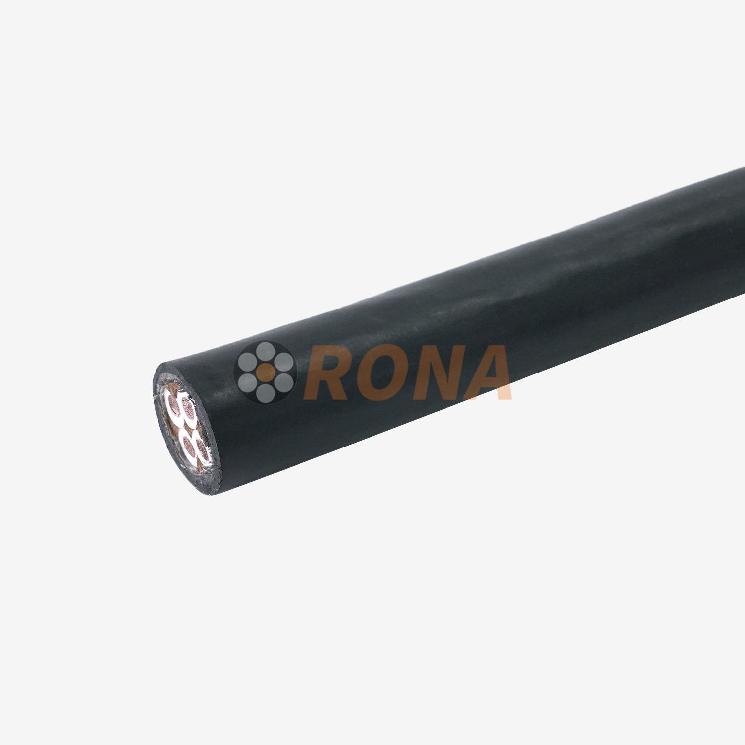
Steel Wire Armor (SWA): This is the best practice for multi-core configurations. The galvanized steel wires provide exceptional resistance to extreme physical impacts, crushing forces, and tensile stresses encountered during direct burial or heavy industrial routing.
Aluminum Wire Armor (AWA): Single-core configurations require non-magnetic aluminum armoring. If steel were used around a single alternating-current conductor, the magnetic field would induce massive eddy currents within the steel, causing severe magnetic loop induction heating that would quickly destroy the cable.
The final boundary layer is the outer sheathing or jacket. This layer protects the internal components from environmental degradation. Depending on the installation environment, the jacket is typically extruded from PVC, standard Polyethylene (PE), or Low Smoke Zero Halogen (LSZH) compounds. The sheath is customized to provide resistance against moisture, ultraviolet radiation, chemical exposure, and mechanical abrasion, ensuring the internal layers remain pristine throughout the operational lifespan.
Evaluating power transmission infrastructure requires a strict analysis of thermal, electrical, and mechanical specifications. The standard operating temperature limit for cross-linked polyethylene is 90°C. This means the conductor can continuously carry sufficient current to maintain a 90°C temperature without degrading the surrounding insulation. During emergency overload conditions, the material can safely withstand temperatures up to 130°C for limited durations. In the event of a catastrophic grid fault, the short-circuit temperature limit reaches 250°C. These elevated thermal limits directly translate to higher ampacity; for the exact same conductor cross-section, a cross-linked polyethylene system can carry significantly more power than older thermoplastic alternatives.
Electrical and dielectric properties further define the efficiency of the system. The material exhibits a very low dielectric constant and an exceptionally low dissipation factor. These characteristics mean that the insulation absorbs and wastes very little electrical energy as heat when subjected to alternating current fields. Furthermore, the high insulation resistance minimizes leakage current. When transmitting power over long distances, these factors are critical for minimizing power loss, ensuring that the maximum amount of generated electricity reaches the end user efficiently.
Environmental and mechanical resilience ensures long-term operational stability. The dense molecular structure provides excellent inherent resistance to moisture ingress and subterranean chemicals found in polluted soils or industrial run-off. When formulated with additives like carbon black, the outer sheathing gains robust UV radiation resistance for exposed outdoor installations. Mechanically, the cables demonstrate high tensile strength, abrasion resistance, and impact durability. These traits are crucial during the installation phase, where cables are subjected to immense pulling tensions and physical scraping as they are drawn through conduits or laid into trenches.
Selecting the correct insulation material requires comparing cross-linked polyethylene against legacy and alternative compounds to determine the optimal performance ratio for a specific project.
Feature | XLPE | PVC | EPR | PILC |
|---|---|---|---|---|
Continuous Temp Limit | 90°C | 70°C | 90°C | 65°C - 80°C |
Short Circuit Limit | 250°C | 160°C | 250°C | Varies (Low) |
Flexibility | Moderate | Moderate | High | Low (Rigid) |
Dielectric Loss | Very Low | High | Medium | Low |
Moisture Resistance | High (TR variants) | Medium | Excellent | Poor (Requires Lead) |
When comparing XLPE vs. PVC (Polyvinyl Chloride), the thermal limits are the most prominent differentiator. PVC is restricted to a 70°C continuous operating temperature and a 160°C short-circuit limit, severely restricting its ampacity compared to the 90°C and 250°C limits of cross-linked polyethylene. PVC is generally used for low-voltage, indoor, or light-commercial applications where loads are predictable and environmental stress is low. Cross-linked polyethylene is mandated for high-voltage and outdoor infrastructure. Additionally, environmental impact plays a role; PVC contains halogens that release toxic, corrosive smoke when burned. Cross-linked polyethylene inherently lacks halogens, making it safer for enclosed spaces when paired with an LSZH jacket.
Evaluating XLPE vs. EPR (Ethylene Propylene Rubber) involves assessing flexibility and dielectric performance. EPR is a highly flexible rubber compound, which is highly beneficial when routing heavy cables through tight spaces, complex conduit bends, or in applications requiring frequent movement. However, cross-linked polyethylene generally has lower dielectric losses than EPR. This lower loss profile makes it vastly superior for extra-high-voltage transmission, where efficiency over long distances is paramount. While EPR has historically shown better inherent resistance to water treeing, modern advancements in cross-linked formulations have largely closed this gap.
The transition from PILC (Paper Insulated Lead Covered) networks to modern systems highlights significant technological advancement. Legacy PILC systems rely on oil-impregnated paper wrapped in a heavy lead sheath. Contrast the immense weight, complex and highly specialized jointing procedures, and severe environmental hazards of oil leaks associated with PILC against modern installations. Cross-linked polyethylene offers a lightweight, low-maintenance, and environmentally safe alternative that eliminates the risk of soil contamination from leaking dielectric fluids.
The robust technical profile of these cables makes them indispensable across various infrastructure sectors. In High-Voltage (HV) and Extra-High-Voltage (EHV) transmission, utility-scale power grids and substations rely entirely on this insulation technology. The ability to handle massive voltage loads with minimal dielectric loss ensures that power generated at remote facilities can be transported to urban centers efficiently. The high thermal limits allow grid operators to push more current through existing corridors during peak demand periods without risking catastrophic insulation failure.
Underground and submarine power networks represent another primary application. Direct burial installations subject cables to constant moisture, soil pressure, and potential rodent damage. Subsea links connecting offshore wind farms or bridging islands face extreme hydrostatic pressure and corrosive saltwater. In these environments, the structural anatomy—specifically the combination of pure dielectric barriers, specialized moisture-blocking tapes, extruded lead or metallic sheaths, and heavy steel armoring—ensures uninterrupted power flow. The insulation maintains its integrity even when submerged, provided the outer protective layers remain intact.
Industrial, mining, and renewable energy sectors present unique operational challenges. Solar farms and wind turbine interconnects experience fluctuating power loads and constant exposure to extreme weather. Heavy manufacturing plants and petrochemical refineries subject infrastructure to constant chemical exposure, high ambient temperatures, and mechanical vibrations. In these demanding use cases, the chemical resistance, thermal stability, and ruggedized outer sheathing of the cables provide the necessary reliability to keep industrial processes running safely.
Procuring high-voltage infrastructure requires rigorous vetting of manufacturers and strict adherence to technical specifications. Buyers must verify compliance with non-negotiable industry standards. Certifications such as IEC 60502 for medium voltage, IEC 60840 for high voltage, ICEA S-94-649, AEIC CS8, and IEEE standards ensure the product has been designed and tested to withstand recognized operational stresses. Manufacturers unable to provide comprehensive documentation proving compliance with these specific standards present an unacceptable risk to grid reliability.
Selecting the correct conductor and screening configurations is the next procurement step. Project engineers must evaluate the choice between stranded aluminum conductors and copper conductors based on the specific installation constraints. Aluminum offers a lightweight solution for long overhead or direct-buried runs, while copper provides higher conductivity and a smaller diameter for space-restricted environments. Furthermore, buyers must verify the inclusion and quality of semi-conductive conductor screens and insulation screens in all MV and HV configurations to ensure electrical stress is adequately equalized.
Quality assurance and factory testing separate premium manufacturers from unreliable suppliers. Buyers must demand detailed factory acceptance test reports. Critical tests include Partial Discharge (PD) testing, which verifies the absence of microscopic voids within the insulation that could cause premature failure. Hot Set tests confirm the degree of cross-linking is sufficient to prevent melting under thermal stress. Finally, rigorous voltage withstand tests ensure the completed cable can handle electrical loads significantly higher than its rated capacity without dielectric breakdown.
Even the highest quality materials will fail if installation protocols are ignored. Mechanical stress and bending radius limits are the most common causes of installation damage. Manufacturers specify strict minimum bending radius requirements based on the cable diameter and armoring type. Forcing a cable into a bend tighter than this radius will cause micro-cracking in the insulation, deformation of the semi-conductive screens, or snapping of the metallic armor. These hidden defects inevitably lead to localized electrical stress and eventual catastrophic failure once the system is energized.
Splicing, terminations, and jointing represent the most vulnerable points in any electrical network. Unlike simple low-voltage wiring, terminating high-voltage networks requires specialized skills, clean environments, and precision termination kits. The semi-conductive screens must be stripped back at exact measurements to control the electrical field at the joint. Poorly executed joints inevitably lead to partial discharge, tracking, and rapid insulation degradation. Utilizing certified jointers and high-quality stress-control accessories is non-negotiable for system longevity.
Water treeing mitigation remains a critical consideration for subterranean installations. Historically, standard cross-linked polyethylene was vulnerable to "water treeing"—a phenomenon where microscopic moisture ingress combined with electrical stress causes microscopic, tree-like fractures in the insulation, eventually leading to dielectric breakdown. To address this historical vulnerability in wet environments, manufacturers developed Tree-Retardant XLPE (TR-XLPE). This modern mitigation strategy incorporates specialized additives into the polymer matrix that actively inhibit the formation and growth of water trees, significantly extending the lifespan of direct-buried networks.
Audit your current electrical infrastructure to identify legacy cables vulnerable to thermal degradation or moisture ingress.
Consult with a licensed electrical engineer to determine the exact voltage ratings, conductor sizing, and armoring required for your specific routing paths.
Request detailed specification sheets, partial discharge test results, and compliance certificates from shortlisted manufacturers.
Verify that your chosen installation contractors hold specific certifications for high-voltage splicing and termination procedures.
To successfully eliminate these operational vulnerabilities and secure a reliable supply chain, project teams must partner with an experienced, high-tier production specialist. As an established leader in global transmission infrastructure engineering, RONA designs and develops advanced, fully certified XLPE cable configurations optimized for heavy industrial, subterranean utility, and high-voltage grid environments. Their high-performance manufacturing lines utilize premium polymer raw compounds and extensive factory acceptance testing to eliminate dielectric impurities, ensuring maximum asset lifespan and uncompromised power system uptime.
A: Under normal operating conditions, these cables typically offer a lifespan of 30 to 40 years. This longevity is heavily contingent on proper installation practices, strict adherence to bending radius limits, and protection from extreme environmental factors beyond the cable's specified design limits.
A: Yes, they are highly suitable for direct burial applications. However, direct burial requires appropriate mechanical protection, such as Steel Wire Armor (SWA), to prevent crushing and physical damage. In high-moisture soils, utilizing Tree-Retardant formulations is strongly recommended.
A: TR-XLPE stands for Tree-Retardant Cross-Linked Polyethylene. It is necessary in wet underground environments to prevent "water treeing," a degradation process where moisture and electrical stress create microscopic fractures that eventually cause dielectric breakdown.
A: They are preferred because they possess significantly higher thermal limits (90°C continuous, 250°C short-circuit) compared to PVC (70°C continuous, 160°C short-circuit). They also offer superior dielectric strength and lower electrical losses, which are critical for high-voltage transmission.
A: Yes, terminating medium and high-voltage networks requires specialized stress-control kits and precise stripping of the semi-conductive screens. Incorrect termination leads to concentrated electrical stress, partial discharge, and rapid joint failure, requiring highly trained personnel for installation.